Relax a goal with a pose cloud
By default Move requires a destination pose, which defines where the end effector must
move to, and the planner holds the end effector to it tightly. For many tasks that is more
precise than needed. Dropping a part into a bin, sanding a flat surface, or pointing a
camera at an injection molding station all have different tolerance requirements for the destination pose,
and demanding tight tolerances on the target pose can lead to issues. An over-constrained goal makes the planner work harder, fail more often, and sometimes reject a goal that would have been valid for the task.
A pose cloud replaces the exact goal with a region of acceptable poses. You
give the planner a target pose plus a set of tolerances, and any pose within
those tolerances is considered valid. This page explains what a pose cloud
relaxes and how to use a pose cloud with the motion service.
When to reach for a pose cloud
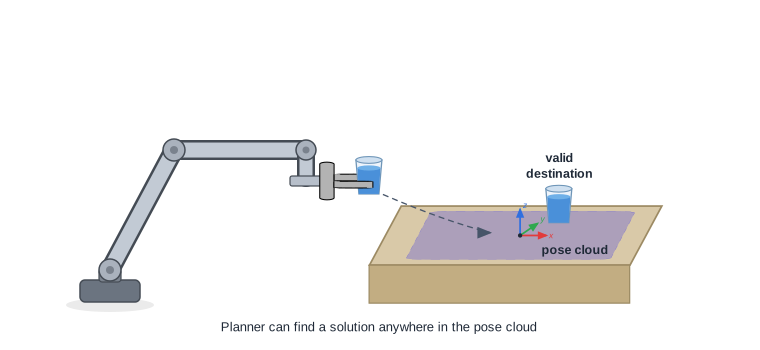
- Target regions. When any spot in an area is an acceptable place to move, use a pose cloud. For example, place a cup anywhere on a clear area of the table.
- Grasp ranges. When an object can be grasped from a range of positions or rotations, a pose cloud lets the planner choose a reachable grasp. For example, grasp a cup that may sit at any rotation about its vertical axis.
- Dynamic collisions. When the target area may contain obstacles, a pose cloud lets the planner place the object at a clear spot while avoiding collisions at the destination.
- Kinematic constraints. When a goal fails or plans slowly because the arm struggles to reach that exact pose, relaxing the destination tolerance enlarges the solution space and often turns a failing plan into a success.
Pose clouds are powerful when coupled with motion constraints: together they describe the motion you want without pinning down the destination exactly. Moving a cup of water is a good example. You define a linear constraint to move the cup along a straight, level path so it does not spill, but you may not know which exact target pose the arm can reach while holding that path. A pose cloud lets the planner choose a destination within a region instead:
Relaxing the destination pose
A pose cloud is modeled as a box with the destination pose at its center. The size of the box
in three dimensions defines a tolerance on the goal pose, and the orientation and Theta components define a
rotation tolerance for the end effector frame. The destination may land anywhere within the
box and rotation tolerance.
&referenceframe.PoseCloud{
    X:     50, // 50 mm of slack in x
    Y:     50, // 50 mm of slack in y
    Theta: 90, // up to 90 degrees of rotation about the orientation axis
    // Z, OX, OY, and OZ are omitted, so they default to 0 and stay exact.
}
| Field | Units | Relaxes | Default |
|---|---|---|---|
X, Y, Z | mm | Position along each axis of the goal pose’s frame | 0: position held exact |
OX, OY, OZ | unitless | The orientation vector components (the direction the tool points) | 0: direction held exact |
Theta | degrees | Twist about the orientation axis | 0: rotation held exact |
A tolerance of zero on a field holds that component to the exact target value; a
larger tolerance gives the planner more room on that component. You relax only what
the task allows: a part dropped into a wide bin can take large X and Y
tolerance while keeping Z tight, and a tool that may spin freely about its axis
can take a large Theta while keeping its pointing direction fixed.
The position tolerances (X, Y, Z) are millimeters and Theta is degrees. The
orientation-vector tolerances (OX, OY, OZ) are unitless deviations of the pointing
direction on a unit sphere, not angles, and 0 holds a component exact. On its own, a value
of 1 on OX or OY accepts any value for that component. OZ is checked as 1 - OZ, the
distance from the goal’s pointing direction, so 1 accepts any direction within 90 degrees
of the goal’s and 2 accepts any direction. Because the pointing direction is a unit vector
(its components satisfy OX² + OY² + OZ² = 1), these leeways are coupled: more room on one
component leaves less on the others, and a wide orientation leeway interacts with Theta,
so a tolerance that is safe at a small rotation can let the tool tip too far at a larger one
(a held cup starts to spill).
Orientation vector normalization: If you build a goal pose whose orientation vector is
unset or all-zero (OX:0, OY:0, OZ:0), Viam normalizes it to the default OX:0, OY:0, OZ:1
before the leeways apply. A wide pose cloud is then measured against that default pointing
direction, not the one you intended, so set the goal’s orientation explicitly and verify the
resulting plan.
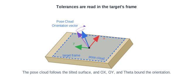
Tolerances are measured in the goal pose’s frame
The tolerances are evaluated in the frame of the goal pose itself, not in world
coordinates and not in the goal’s parent frame. The frame’s origin is the goal position,
its Z axis is the goal’s pointing direction, and its X and Y axes follow from the goal’s
orientation, including Theta. X, Y, and Z are offsets along those axes, and OX,
OY, and OZ describe the candidate’s pointing direction in that frame, so OZ bounds
how far the pointing direction turns away from the goal’s (1 - cos of the angle, in any
direction) and OX and OY bound its sideways components.
Theta bounds the twist about the goal’s Z axis. Tilting the pointing direction, in any
direction, uses none of it.
Consider a gripper approaching an inclined surface with its tool pointing into the surface,
along the surface normal. The goal frame’s Z axis is then normal to the surface, and its X
and Y axes lie in the surface: make X and Y large so the tool can ride along the surface,
and keep Z tight so it stays on the surface. These tolerances follow the tilt of the
surface directly. When the goal points another way, for example horizontally for a side
grasp, work out which goal axis each world direction maps to before you set the tolerances.
Use a pose cloud with the motion service
A pose cloud travels with the destination pose. In Go, attach the pose cloud to the destination with
NewPoseInFrameWithGoalCloud, then pass that destination to Move. The pose is
the center of the region and the PoseCloud is the tolerance around it. This example adds a
linear constraint, so the cup travels a straight, level path for the whole motion, not only at
the goal.
import (
    "github.com/golang/geo/r3"
    "go.viam.com/rdk/motionplan"
    "go.viam.com/rdk/referenceframe"
    "go.viam.com/rdk/services/motion"
    "go.viam.com/rdk/spatialmath"
)

// Place the cup somewhere on the table, held from the side. The exact spot and
// the cup's rotation about vertical do not matter, but it must stay upright.
// The tolerances are measured in the goal pose's frame. For this goal, that
// frame's Z axis is the pointing direction (the table's +X), its X axis is the
// table's +Z (up), and its Y axis is the table's -Y.
destination := referenceframe.NewPoseInFrameWithGoalCloud(
    "table", // the goal pose is expressed in the table frame
    spatialmath.NewPose(
        r3.Vector{X: 0, Y: 0, Z: 0}, // center of the region, on the table surface
        // Grasp from the side: the tool points horizontally across the table (OZ: 0).
        // OX: 1 sets a definite pointing direction, so the pose cloud's OX and OY leeway
        // is measured from the grasp you intend, not a normalized default.
        &spatialmath.OrientationVectorDegrees{OX: 1, OZ: 0, Theta: 180},
    ),
    // Each tolerance is [-value, +value] in the goal pose's frame.
    &referenceframe.PoseCloud{
        X:  0,    // goal X is up: hold the cup on the surface
        Y:  75,   // mm of slack across the table (goal Y)
        Z:  75,   // mm of slack across the table (goal Z, the pointing direction)
        OX: 0.05, // the pointing direction's vertical part: keep the tool level, so the cup stays upright
        OY: 1,    // the pointing direction's horizontal part: any amount...
        OZ: 2,    // ...and up to a half turn from the goal's, so the approach may come from any side
        // Theta stays 0, so the tool does not roll and tip the cup. Once the approach
        // swings away from the goal, a tilt also reads as twist, so Theta 0 rejects it too.
    },
)

// Move the cup along a straight path (within 5 mm) and keep it level (within 5 degrees)
// the whole way, not just at the goal.
constraints := &motionplan.Constraints{
    LinearConstraint: []motionplan.LinearConstraint{
        {LineToleranceMm: 5, OrientationToleranceDegs: 5},
    },
}

_, err = motionService.Move(ctx, motion.MoveReq{
    ComponentName: "my-gripper",
    Destination:   destination,
    Constraints:   constraints,
})
if err != nil {
    logger.Fatal(err)
}
Available through the Go SDK
The Go SDK provides NewPoseInFrameWithGoalCloud to attach a pose cloud to the destination.
The goal cloud travels in the Move request, so the motion service honors it on the server.
What’s next
- Configure motion constraints: restrict the path between poses, the complement to relaxing the goal.
- Move through waypoints: use pose clouds for the waypoints where close enough is fine.
- How motion planning works: why a larger solution set makes the search succeed more often.
Was this page helpful?
Glad to hear it! If you have any other feedback please let us know:
We're sorry about that. To help us improve, please tell us what we can do better:
Thank you!